This is a quick post to show my progress on making an improved STM32F board inspired by LeafLabs Maple-mini, and Siy’s mini48. I’ll explain more about the changes and rationale in a future post. WARNING: this board has not been assembled and tested. So please don’t assume it’s finished and ready to be used.
The main aim was to be bootloader and code compatible with Maple-mini. I believe that’s satisfied by retaining the same signal pins, for the same purposes. All the signals on the pins are the same signal sources with the same names and positions.
One aim was to retain pin compatibility with Maple-mini. However, as I made changes, I decided that the one of the defects of Maple-mini is the power supply. So Maple-mini’s analogue output voltage (the av+ pin) has been replaced by a connection to the higher-capacity digital power regulator. I’ll explain the detail later, but the key point is, for most uses of Maple-mini the pin-change is transparent. So I hope it is close-enough to pin compatible.
The main differences are:
- Redesign Maple-mini’s 4-layer PCB, as simpler, Double-sided PCB
- Single-sided Surface Mount Devices (SMD), for simpler DIY assembly
- Larger 0805 parts, replacing 0402 parts, easier (for me) to make
- Much higher capacity Voltage regulator, aim is full power from 9V input
- Polyfuse protecting Host’s USB-sockets power
- USB Electro-Static Discharge (ESD) protection for Host-USB socket
- More compact USB termination
- Simplified USB ‘pull-up resistor’; signals ‘USB device type change’
- Through-hole USB socket intended to be more robust than SMD socket
When I started, I didn’t expect to achieve Maple-mini’s useful 0.6″ row spacing of header pins. I was using relatively modest PCB Design Rules of 8mil track and space (about 0.2mm track & space).
Siy wrote that he’d packed an 48 pin STM32F into a 0.5″ pitch board! He is amazingly good at this stuff. Inspired by Siy, I tried using a finer 6mil track and cleaeence (just over 0.15mm).
Here’s the PCB. The header pins are the same pitch and distance apart as Maple-mini (or as a PDF: Orone-mini-T6-v0Xr001):
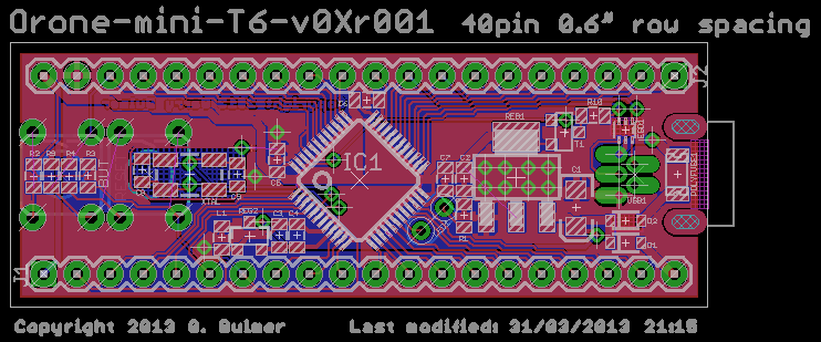
Because the header pins are physically identical, and signal identical, it should ‘just plug in’ to a circuit using Maple-mini. The only change on the header pins is replacing ‘av+’ with the normal 3.3V ‘vcc’. As I wrote, I made this change to enable the board to safely run at higher input voltages (Vin) than Maple-mini. However, I would expect the change to be invisible for most users.
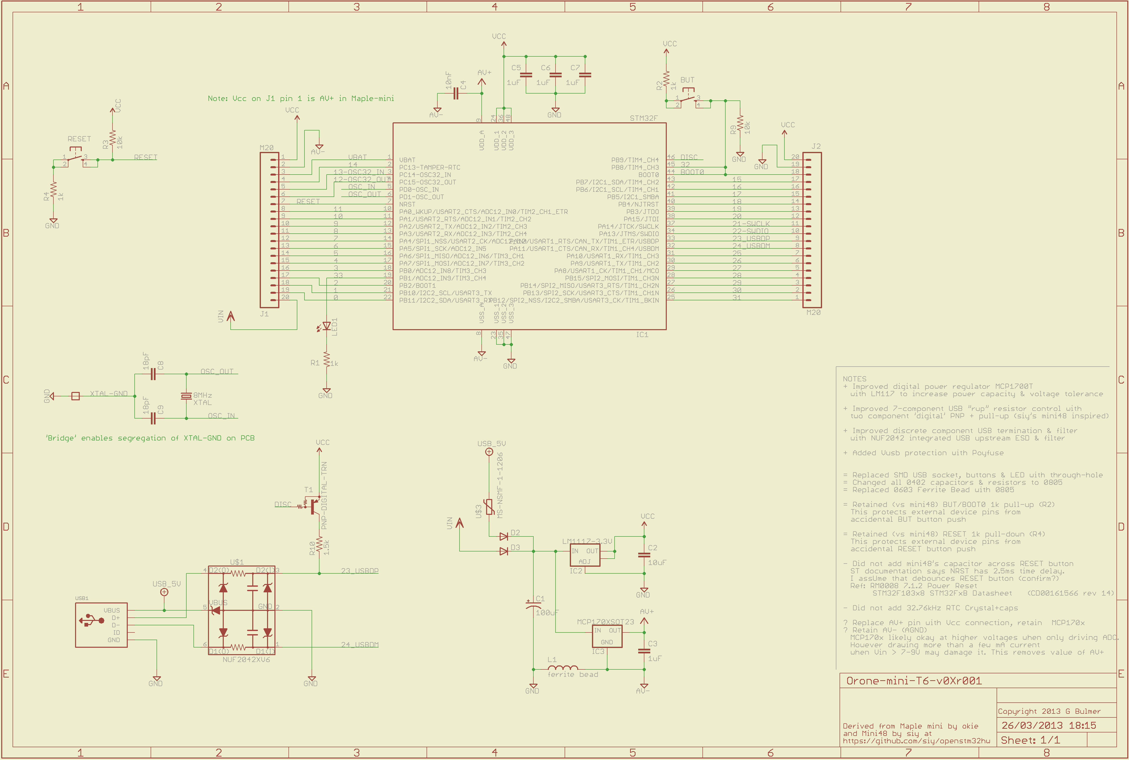
There are quite a lot of changes to the schematic. So here is the schematic, including some notes about changes (or as a PDF Orone-mini-T6-v0Xr001.sch):
I intend to post more explanation, and upload the Eagle CAD to github, soon. I hope this is useful to folks.

March 27, 2013 at 3:34 pm |
IMHO, one of the issues that plagued leafLabs’ products was the inconsistent support across different for their USB-based (DFU protocol) bootloader. Much of those problems were due to DFU implementation that were not per the DFU protocol. There were a number of discussions about possible changes on leaflabs’ forums. The use of one of the better-supported USB class drivers (for instance, the CDC class) seemed the cleanest across the dev. platforms of interest.
FYI, NXP’s LPC1343 chip has ROMed code that, when activated, makes the chip’s flash memory look like a tiny USB thumb drive containing a single file. When used in this manner, one can re-write the chip’s flash memory by replacing that one file. IMHO, that’s a pretty good way of making a device un-brick-able.
March 28, 2013 at 6:08 pm |
ursine1 – Thank you very much for your thoughtful comments. I apologise for my slow reply. I think your points deserve a full response. Unfortunately I’m not feeling well. So I hope its acceptable for me to come back in when I am better, and give a proper comment?
I agree that LeafLabs USB bootloader has issues, especially on Windows. However things have improved.
March 28, 2013 at 9:06 pm |
@ourduino,
First off, I hope you feel better ASAP! I offered my comments mainly to ensure that you were aware of the bootloader issues. Reply (or not) when and how you please. From the hardware perspective, so long as whatever bootloader you use is USB based, I *think* the circuit design would be independent of what USB driver is needed on the host side.
Re hardware, I believe the USB mini connector on the Maple mini has been deprecated in favor of the USB micro connector. If you’re going for mechanical plug&play, that’s a legit reason to stick with the deprecated mini connector.