Archive for the ‘Uncategorized’ Category

Improving Maple Mini (part 2)

March 31, 2013

Tekwizz colleagues gave me feedback on Orone-mini, my current attempt to improve Maple-mini. They suggested that the board should focus more on being practical for people, especially relatively inexperienced makers, to assemble by hand, and less on being small. We agreed this mainly means using larger SMD parts which are easier to handle. Hence, I have made the components even larger than Orone-mini, which itself already uses much larger components than Maple-mini.

Another change to help make the board easier to assemble is using bigger pads and wider tracks. This is not about making a ‘DIY’ Printed Circuit Board (PCB), but about soldering parts onto it. I’ve recently worked with a lot of people who are beginners to soldering, and they have started with through hole parts. They are making a quite finely detailed board (not designed by me:-). This experience proved it is easy to overheat pads and tracks with a soldering iron, melting the glue, and detaching the copper from the board. This can be very awkward to fix or workaround. So the Orone-mini board has wider pads and tracks around through-hole soldered parts, increasing the area of copper, and hopefully making it more robust for people to assemble.

Increasing the size of parts means increasing from the Maple-mini’s 0402, and Orone-mini’s 0805, to 1206 size Surface Mount Devices (SMD). This means all of the Maple-mini 0402 size parts, that is 0.04 inch x 0.02 inch, or approximately 1mm x 0.5mm, are now 1206 size parts, which are 0.12″ x 0.06″, or approximately 3mm x 1.5mm. So each part increase to nine times the area of the Maple-mini part. I also increased the size of the protection diodes to twice their previous size. The transistor, regulators and Integrated Circuits (ICs) are the same as before. The transistor and small regulator are about the same size as a 1206 part, and there is no other package for either IC. The through hole parts are unchanged in size; I’ve used some of them with beginners, and they seem to be okay.

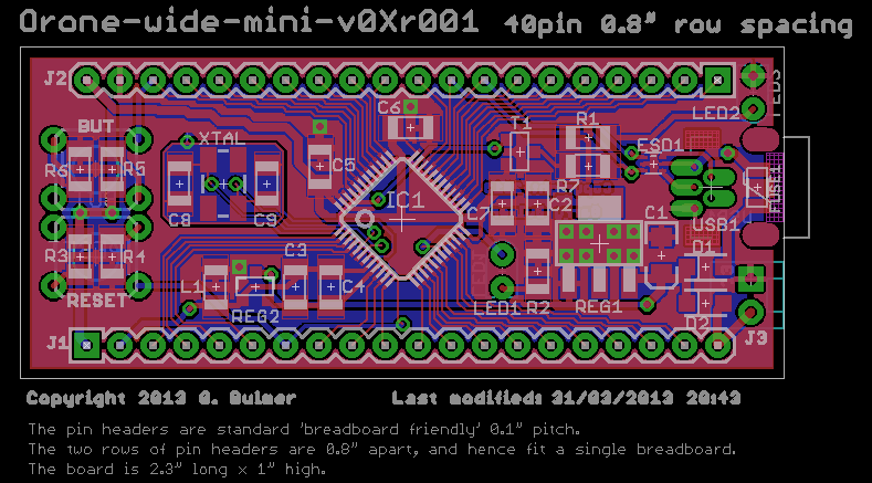
Not too surprisingly, I couldn’t fit the bigger-size components onto a Maple-mini size PCB. So the PCB has increased in size by 0.2 inches in each direction. The 0.1 inch pitch header pins are also 0.2 inches further apart, so now at 0.8 inches. It is still quite small at 2.3 inches x 1 inch. I am currently calling this ‘Orone-wide-mini’, though I quite like ‘Orone-mini-w’, or ‘Orone-mini-08’ (to identify the header spacing). Any suggestions?

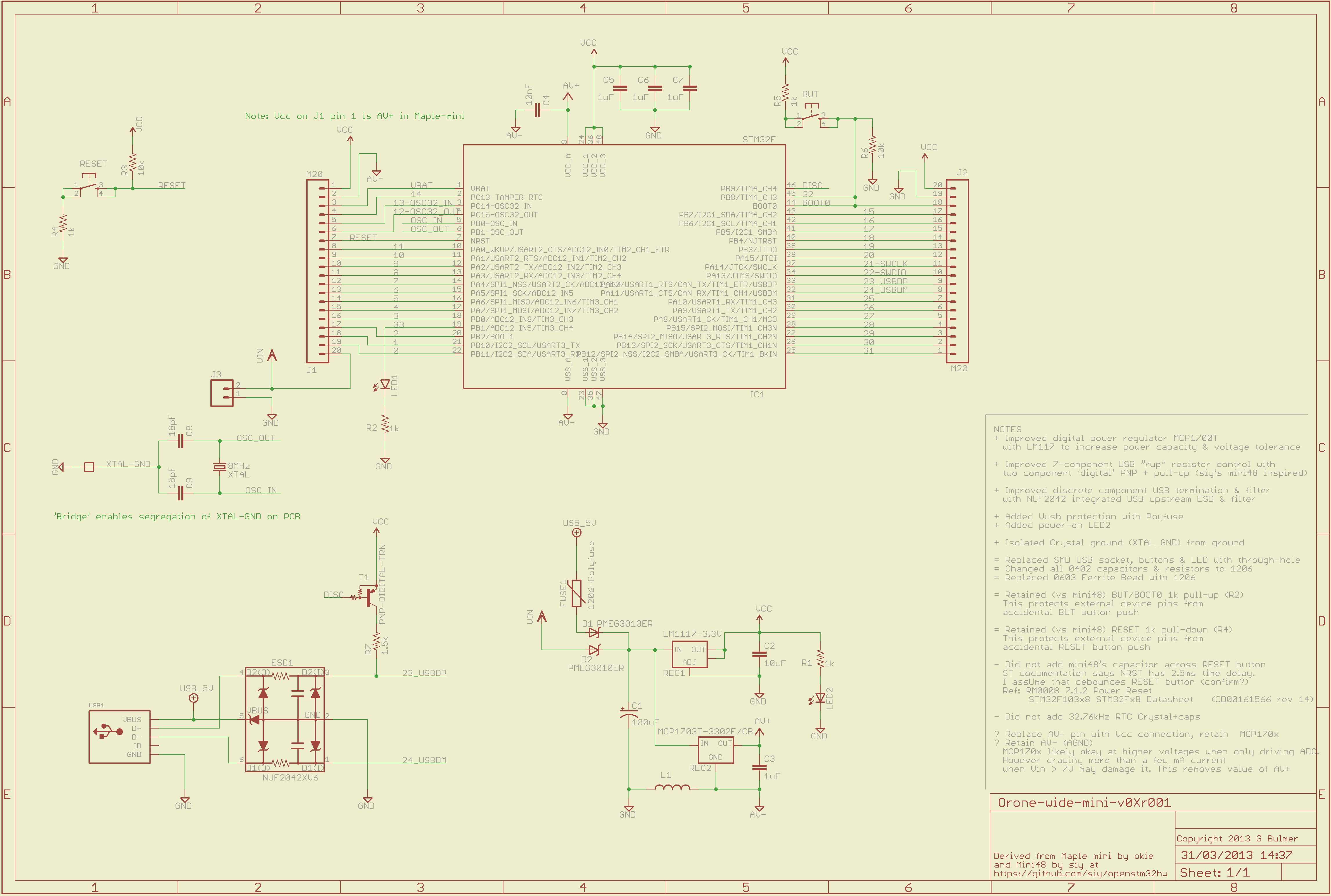
Increasing the board size creates quite a lot of unused area on the bottom of the PCB, which is really the ‘Top’, because it’s the side people will see when using it. This bigger area gives more space for the ‘Top’ silkscreen, so that is slightly bigger. However, it also provided enough space to fix two other Maple-mini deficiencies; Orone-wide-mini has a ‘Power On’ LED, and a two-pin Molex socket for ‘External Power’.

The ‘External Power’ 2-pin Molex socket is on the same 0.1 inch grid as the boards main pin headers. So hopefully anyone intending to use Orone-wide-mini on their own strip-board circuits should find it practical to use 0.1 inch pin headers in the External Power holes and provide their own external power.

Finally, the component-side silk screen, which carries the names of components, has been increased in size, hopefully making it easier to use while assembling the board, and reducing the need for a separate assembly guide ‘component map’.

The header pins are as before; signal identical, and voltage identical with Maple-mini. So the existing Maple-mini-bootloader should ‘Just Work’ (TM 🙂

Here is a draft version of the ‘Orone-wide-mini’ board (or as pdf with comments Orone-wide-mini-v0Xr001):

Orone-wide-mini-v0Xr001
Here is the schematic with the new additions of Power-on LED and External Power Molex socket. (or as pdf Orone-wide-mini-v0Xr001.sch):

Orone-wide-mini-v0Xr001.sch
This rework has set me back a bit, and I have been ‘under the waether’, so I now hope to have checked and uploaded the CAD in a couple of days.

Summary: Orone-wide-mini uses larger components, along with bigger tracks and pads and better compnent-side silk screen to help make it ‘hand assembly friendly’. It adds a Power-on LED, an External Power 2-pin Molex socket, and larger ‘user side’ silk screen, hopefully making it more useable. It retains Maple-mini signal and voltage compatible pin headers.

WARNING: This has not yet been made, so please do not assume it even works.

Improving Maple Mini (part 1)

March 26, 2013

This is a quick post to show my progress on making an improved STM32F board inspired by LeafLabs Maple-mini, and Siy’s mini48. I’ll explain more about the changes and rationale in a future post. WARNING: this board has not been assembled and tested. So please don’t assume it’s finished and ready to be used.

The main aim was to be bootloader and code compatible with Maple-mini. I believe that’s satisfied by retaining the same signal pins, for the same purposes. All the signals on the pins are the same signal sources with the same names and positions.

One aim was to retain pin compatibility with Maple-mini. However, as I made changes, I decided that the one of the defects of Maple-mini is the power supply. So Maple-mini’s analogue output voltage (the av+ pin) has been replaced by a connection to the higher-capacity digital power regulator. I’ll explain the detail later, but the key point is, for most uses of Maple-mini the pin-change is transparent. So I hope it is close-enough to pin compatible.

The main differences are:

  • Redesign Maple-mini’s 4-layer PCB, as simpler, Double-sided PCB
  • Single-sided Surface Mount Devices (SMD), for simpler DIY assembly
  • Larger 0805 parts, replacing 0402 parts, easier (for me) to make
  • Much higher capacity Voltage regulator, aim is full power from 9V input
  • Polyfuse protecting Host’s USB-sockets power
  • USB Electro-Static Discharge (ESD) protection for Host-USB socket
  • More compact USB termination
  • Simplified USB ‘pull-up resistor’; signals ‘USB device type change’
  • Through-hole USB socket intended to be more robust than SMD socket

When I started, I didn’t expect to achieve Maple-mini’s useful 0.6″ row spacing of header pins. I was using relatively modest PCB Design Rules of 8mil track and space (about 0.2mm track & space).

Siy wrote that he’d packed an 48 pin STM32F into a 0.5″ pitch board! He is amazingly good at this stuff.  Inspired by Siy, I tried using a finer 6mil track and cleaeence (just over 0.15mm).

Here’s the PCB. The header pins are the same pitch and distance apart as Maple-mini (or as a PDF: Orone-mini-T6-v0Xr001):

Orone-mini-T6-v0Xr001

Because the header pins are physically identical, and signal identical, it should ‘just plug in’ to a circuit using Maple-mini. The only change on the header pins is replacing ‘av+’ with the normal 3.3V ‘vcc’. As I wrote, I made this change to enable the board to safely run at higher input voltages (Vin) than Maple-mini. However, I would expect the change to be invisible for most users.

There are quite a lot of changes to the schematic. So here is the schematic, including some notes about changes (or as a PDF Orone-mini-T6-v0Xr001.sch):

Orone-mini-T6-v0Xr001.sch

I intend to post more explanation, and upload the Eagle CAD to github, soon. I hope this is useful to folks.

Joule thief workshops

July 25, 2012

We spent a some time at the first Tekwizz ‘hands-on-workshop’ to identify practical projects that we’d be interested in making. One project is the ‘Joule thief’, so I did a bit of research to figure out how to make it at workshop-scale.

A Joule thief is a kind of DC-DC converter. It steps up the voltage of one non-rechargeable ‘dead’ battery sufficient to light a white LED (over 3V). It’s claimed it lights for 10 to 20 hours. A ‘dead’ battery is one which has run down to a voltage too low to power normal domestic electronics. I think it’s best not to use rechargeable batteries with a Joule thief, because it will run a rechargeable down so low it will be damaged.

The Joule is the SI unit of energy (or work), so it is quite a nifty name.

This is one of the first search hits: http://www.bigclive.com/joule.htm

The Wikipedia Joule thief page has some good information on how it works.

Most (all?) electronic step-up voltage converters use an inductor for energy storage, and some sort of oscillator to drive a transistor switch. The Joule thief is rather clever because it uses the oscillations of the step-up inductor to switch the transistor on and off. So it is beguilingly simple.

The components are:

  • white LED, which are easy to get off-the-shelf,
  • ferrite core used to wind the inductors,
  • wire, which winds on the ferrite core to make the inductor,
  • BC549C transistor (or better), used to switch the inductor,
  • 1K resistor, used to pull the transistor on.

The resistor and a transistor are relatively low-cost and easy to get, though some authors recommend a better transistor than the original Joule thief BC549 (which is hard to find anyway; places like RS have discontinued them). For example look at http://quantsuff.com/ or http://www.instructables.com/id/Joule-Thief-LED-circuits/step6/The-Usual-Suspects/

The recommendation is to use a transistor with a lower collector-to-emitter saturation voltage, Vce(sat), than the 0.6V of the BC549. The aim is to maximise the (already low) battery voltage across the inductor. This should make the Joule thief more efficient, and run for longer. I don’t believe a Joule thief is as efficient as a specialised integrated circuit, and I think the spirit is we’re getting almost free power, so I don’t feel it is worth fretting too long about this. There are suitable sub-20p transistors with 0.3V Vce(sat) or less, half the Vce(sat) of the BC549.

A significant cost is the 38swg (0.15mm) enamelled/insulated wire. A Joule thief only needs 1 metre, so it is actually quite cheap, but the smallest reel I found was almost 2,000 metres, at about £15+VAT. Good if you’re doing workshops for hundreds but a bit of a waste for dozens.

The other problematic part is ferrite inductors. Low-cost (sub 10p) ferrite cores have a central hole 2mm or less in diameter (and come in packs of 20 or 10).

I wrote to ‘Big Clive’ and he replied, saying the Joule thief is pretty robust, and forgiving of component variation. So thinner or thicker wire would be okay.

I found reels of hundreds of metres of 34/35 swg for under £7 (+VAT), and 42/43swg even cheaper. The extra thickness might make it a bit stronger while winding the inductor, and the thinner wire might be easier to thread through cheap, small hole, ferrite cores. We’ll need to do some experiments.

Clive recommended trying to scavenge a ferrite core from a broken Compact Fluorescent Light (CFL). This would be good because it is free, but IIRC, CFLs contain some quite unpleasant chemicals, so be careful, and if you are at all concerned, don’t try. If a group of folks want to all run a Joule thief workshop, investing in a 10, 20 or even 100 pack of ferrite cores might make more sense.

Another obstacle to running workshops is a ready supply of ‘dead’ batteries. I usually have a few hanging around, but not 20 or so, which might be needed for a workshop.

I spoke to my local Sainsbury’s who have a battery recycling ‘drum’. I explained that we are interested in helping local schools and community make their own technology. I explained what a Joule thief is, and said we’d like a source of ‘dead’ batteries for workshops. They were supportive and quite enthusiastic. They would like a letter for their ‘local support’ notice board to explain the project to the public. This would give them a record so folks in-store could figure out why we are picking through their battery recycling ‘drum’, and anyone who’d just put batteries in might be lured into a workshop 🙂

So it looks like there are possible solutions to all the obstacles to running Joule thief workshops; though the devil is in the detail, and doing it is the main test.

There are lots of web pages showing a Joule thief using large diameter ferrite cores, and ordinary plastic coated copper wire. Those cores are significantly more expensive than the small ones. There are also Joule thief designs with inductors using no ferrite, though I believe that is less efficient. Please use whatever comes to hand.

This isn’t a definitive approach, just initial thoughts and investigation. I hope it might help folks who’d like to run low-cost scalable Joule thief workshops.

STM32F4 Cortex-M4 is bonkers, and I want one

October 4, 2011

I posted at LeafLabs about ST Micro’s recent release of their ARM Cortex-M4 implementation, the STM32F4, but forgot to post here. I am a geek. I love computer hardware, and microcontrollers are great because I can afford to get them and try to make my own computers.

What could be more fun? Oh, yea, you have  a long list. Okay, let me press on.

There are a few things which microcontroller fans might like about ST Micro’s new product:

1MByte Flash, and 192KBytes of RAM. I remember reading the Unix edition six source, and IIRC, it would run in 128KBytes RAM, and that was a multi-user , multi-process operating system, with a proper hierarchical file system (none of the A: nonsense). That amount of memory is quite luxurious for Arduino users. It is 32 Arduino UNO’s worth of Flash, and 96 Arduino UNO’s worth of RAM.

Floating Point Unit. Modern PC’s have hardware floating point. For some problems, it is much easier to write a solution using floating point numbers than whole numbers (integers). For example manipulating angles, or digital audio signals. A floating point number is one with a decimal point, like 3.1415926, or that is tiny, like 10^-126, a number which makes a yoctosecind seem like an eternity (seriously, the age of the universe, measured in yoctoseconds is only 4.3×10^41 yoctoseconds), or big, like 10^127 (that’s the digit 1, with 127 zero’s after it).

The nifty thing about floating point numbers is they keep track of the position of the floating point for you. Most microcontrollers don’t have floating point hardware, so programs have to do all the bookkeeping and arithmetic in software. You don’t have to write the code because the compiler will do that for you. This can be a bit weird because it looks just the same as integer arithmetic, but the program is bigger and slower.

ARM publish a few benchmarks which suggest Cortex-M processor with hardware floating pont might be 10x faster than the same processor doing floating point arithmetic in software.

That is quite a big deal, if you want to use something like trigonometry, where calculating sine or cosine are themselves a bunch of floating point calculations. We really might see that 10x speed change.

Why do I care? Well, I am very interested in things which might inspire and motivate children and adults to learn programming. Sound and music are an area that lots of people love. Simple notes can be described by sine curves. So it would be very handy to write simple programs which generates values on a sine curve, and pumps them out through a Digital to Analogue Converter (DAC), through an analogue audio chain, so that we can hear it.

Something like:

const float frequency = 440.000; // A above middle C
const int sample_freq = 44100; // CD audio sample frequency, 44.1KHz
const int samples = sample_freq/frequency; // number of samples/cycle
while (true) {
    for (int i=0; i<=samples; i++) { 
        dacWrite( sine(i * 2.0*PI / samples) ); 
        delayMicroseconds(1000000/sample_freq); 
    }
}

That is too rough to work well (the delay might not be accurate enough, and it ignores the time used to do the calculation and loop) but I hope it is enough to illustrate the idea. Fast floating point should make maths and music easier to program.

STM32F4DISCOVERY is the low-cost development kit that STM are offering. Farnell are taking pre-orders, it is £9.26+VAT! They are about $16 in the USA, but I didn’t see any distributors with the stock-arrival date.

That is an amazing price if you were to compare to something that has to be sold at a profit, like an Arduino UNO. Of course ST Micro don’t have to make a profit on this, they might regard it as the cost of a marketing campaign. I much prefer this approach to a fancy, glossy, high visibility marketing campaign. I don’t want to look at fancy ads. I want the product at a price which I can’t ignore. Thank you STM.

I’ll try to pick up again, and mention some of the other nifty stuff, but if your interested, please check out the datasheets and reference manual.

Yoctoseconds are mind boggling

October 3, 2011

My chum Jeff showed me this presentation about creating very short gamma-ray pulses which has quite an interesting ‘time scale’ showing the time that small scale processes take.

It also talks about creating yoctosecond gamma-ray pulses.

Folks may know, light travels at 300,000Km/second, or 3×10^8 m/second (10^8 is supposed to be 10 raised to the power 8 or 100000000)
A hydrogen atom is about 1.1 Ångstrom in diameter, 1.1×10^-10m (10 raised to the power -10, or 0.0000000001)
So, light travels the diameter of a hydrogen atom in 3.6×10^-19 seconds,  0.36 attoseconds (10^-18), or 360 zeptseconds (10^-21 seconds)

A yoctosecond is 10^-24, so light would travel 1/360,000 of a hydrogen atom diameter. Hydrogen atoms are small. Even thinking about the time it takes light to streak cross one is amazing, but a yoctosecond is a tiny time.

If I were going to drive for the next 4 and a bit days, 100 hours, to go between, say, London and San Francisco (on an imaginary road:-), at about 54 miles per hour, that is the first second of the journey.

I find that utterly mind boggling.

PYCON UK. O’Donohoe’s BBC.Codelab is a hoax

September 25, 2011

I went along to PYCON UK 2011 this weekend. I went for a few reasons. One was for a talk about BBC.Codelab. I also wanted to speak to encourage people to get involved in teaching children (and adults) to program. Finally I needed to find out if there are any Python UK members who might help me understand what Python on the STM32F ARM chip might be.

The talk about BBC.Codelab by Alan O’Donohoe, a secondary school head of ICT. I was able to speak to him on Saturday, and he said that he was part of a pilot project by the BBC which would be rolled out April 2012. The project will give every school child their own computer, support and resources. The support was targeted at children and not teachers.

I was flabbergasted. I have had a few conversations with people at the BBC, and have heard no mention of this, so I had to go along. This could be amazing. My hopes and dreams to give every child the opportunity to learn to program, and more importantly, that computers are a vehicle for creation and not just consumption, might be only a few months away! Life changing.

The room was quite small, and was packed, with lots of folks standing. He had the session chair video his presentation, so Tony was focused on Mr O’Donohoe and not the room.  The talk began with a brief history of him becoming excited by programming the BBC micro, but then how he’d spent the last 18 years teaching ICT. He talked of his ‘Damscus moment’ a year ago when he realised he was teaching how to use Microsoft Office, but not how to program applications.  He talked of how he felt he had let the children down. There was warm support in the room.

As people heard the proposed roll-out of millions of computers across UK schools, and tried to ask questions, discussion got more ‘energetic’. He suppressed all attempts to interrupt him. He took no questions, and treated people like they were naughty children . Folks thought it was somewhat amusing, but the another explanation only became clear later. He was ensuring his video was only of him, and no objections or questions. Once he had finished, he stopped the video recording.

Not surprisingly, people active in the Open Source community, and concerned about Computer Science and programming education in schools were very agitated, and wanted to know why the BBC had not engaged with them. Another person thought this announcement must be connected to the RaspeberryPi charity.

One person said that he had been at the September 16th BBC Manchester Barcamp. He said that he thought it wasn’t as presented. At this point Alan got a bit uncomfortable, and said that people may be very unhappy with him. Eventually he said it was all a hoax. People burst from the room, mostly frustrated at the total waste of an opportunity to do something positive. As we left,  Mr O’Donohoe asked people not to reveal it was a hoax.

I was flabbergasted for a second time. Alan said that he had presented the idea at the Manchester Barcamp. He said it had caused a lot of excitement, and claimed several people had congratulated him on the amount of excitement it had created.

I felt so strongly, that I put myself down for two lightning talks. I was hoping to ensure everyone who had overheard earlier fragments of conversations, but not been in the talk, knew it was a hoax. O’Donohoe had put himself down already for a lightning talk, so I assumed he would be revealing the hoax, and apologising for wasting everyone time. I was wrong. He talked about how useful twitter is.

I was stunned. I had expected him to explain his reasons for his hoax. Or apologise for the the hoax. Maybe apologise for consuming everyone’s time when we could just as easily have spent the same time, enthusiasm, talent and experience on making progress on children’s education. So I went ahead and tried to explain the O’Donoue’s BBC.Codelab was a hoax, and that there are several bad things that it might cause, as well as the wasted opportunity.

IMHO, it was genuinely risky to suggest that the BBC had ‘solved’ such a big education problem as teaching all children to program, with such an enormous roll-out of equipment, with so little engagement with one of the communities who might help.

I feel deeply sad that the talk was a hoax, and children will not all have their own computer next April. I am sad that all of our time was wasted, when it could so easily have been applied constructively. It was pretty clear that a lot of people in the Python community care a lot about education. It seems sad that this talk stirred up negative emotions rather than directing a positive outcome, given the level of interest already in the Python community. There is time for the wider Open Source community to get involved and help education move forward, but we need to be constructive rather than fantasists.

I am still pondering what motivated Alan, and whether or not he would have said it were a hoax without the challenge from the Barcamp attendee? Maybe no one can know.

New Arduinos

September 25, 2011

The Arduino team announced some new Arduino’s:
http://arduino.cc/blog/2011/09/17/arduino-launches-new-products-in-maker-faire/

The “Arduino Leonardo” is simpler, and should be significantly cheaper than an Arduino because it uses an ATmega with on-board USB. This looks pretty much like a “Teensy” from PJRC but with an Arduino UNO board layout.

The “Arduino Due” uses an ARM Cortex-M3 processor, in this case an Atmel SAM3U4. Unfortunately, that chip is quite big, 100-pin or 144 pin, so cost might be an issue. Atmel might give them good discounts,. We will see. It is forecast to be available by end of year.

From the brief spec, I think it is a 144-pin part, the SAM3U4E. That gives lots of Input and Output (I/O) pins. I am very interested in small robots, so that is quite big for a micromouse.

Compared to the ARM Cortex-M3 I am working with already, the ST Micro STM32F103, the exciting new feature of the Atmel SAM3U is high-speed USB (480Mbits) on-board, and it runs at 96MHz.

In other STM32F comparisons, I think the STM32F is slightly better for my areas of interest, though I would have to use a 144-pin STM32F part to get the full external memory interface.

The SAM3U does not have any Digital to Analogue Converters (DACs), whereas the comparable STM32F103xC (high density) part has two. Comparable STM32F has three 12-bit Analogue to Digital Converters (ADCs) which is slightly better than the SAM3U4 two ADCs. There is an interface to good quality audio chips called I2S. SAM3U4 has one I2S interface, while STM32F103 has two. What does this all mean? If you want to build audio projects, the STM32F might be a better starting point.

It is extremy useful for robots to keep track of their own position by measuring wheel movement (odometery). The technique often used is the same as older ‘ball’ mice. Internally a ball mouse has two orthogonal small wheels which rotate when the ball rotates. The two orthogonal wheels have slots. Light shines though the slots, and each time the light beam is broken, movement is detected. By using two beams and two sensors on each wheel, it can tell which direction the ball is moving. This technology is a quadrature encoder.

Quadrature decoders are very useful to track and time the quadrature encoder. STM32F103 timers can each implement a quadrature decoder, and hence some parts can provide upto 6. I had thought I’d misunderstood the SAM3U4 datasheet, but Atmel have confirmed it only has one quadrature decoder. This is not an issue, unless you want to build robots which ‘know’ where they are.

I am very pleased that the Arduino team are working on ARM Cortex-M3. I think this will encourage a lot more people to use the 32-bit ARM platform. Coretx-M3 is capable of so much more than the 8-bit ATmega, that I expect a significant flurry of new projects next year when the Arduino Due is fully developed.

Meanwhile, I’ll keep working on STM32F, and watch out for results from the Arduino Due .

Arduino in Schools at DD&T Conference

September 20, 2011

I had the great pleasure of leading two Arduino workshops for the DD&T Conference, on 12 July at Sheffield Hallam University.

I lead two sessions where I spoke about the background of Arduino, and the importance of Open Source. Then everyone got their “hands dirty” wiring up simple electronics and programming the Arduino. The attendees were D&T teachers, D&T support centre consultants and technicians.

Traditionally, schools use some version of the PIC microcontroller, but, I am told, schools teachers are being asked about Arduino. This is an intriguing development. It is good that there are folks out there encouraging education to get involved with Arduino, which has a very different image to the PIC-based systems.

As well as traditional breadboard-based electronics, we also tried Paul Gardiners ‘Explorer” modules. I have designed a simple Arduino shield which plugs into the Arduino, and enabled people to very quickly construct electronic systems using Paul’s electronics modules. Paul has developed almost 50 modules, so there is a lot of scope, and they can be combined to explore and develop an idea quite quickly.

The effect is transformative. Using Paul’s modules, the activity uses most of the time for programming and debugging the code. When I use breadboard-based electronics, I usually find a lot of the time is spent debugging the elctronics.

The sessions were welcomed, and worked quite well, though they were too short to cover as much ground as I would like. We have a solution to this though, because I am doing another workshop for teachers at the weekend.

Dev8D 2010 – Arduino Workshops

April 28, 2010

I had a wonderful time at Dev8D. It was a great event, and I feel privileged to have been able to contribute. Many thanks to Dave Flanders for the invitation, his enthusiasm, and encouragement, and Mahendra Mahey for making it work so well.

I ran three workshops introducing Arduino and basic electronics, and two intermediate, follow on Arduino workshops. To keep costs down, we had 12 complete kits, and asked folks to work in pairs. There were a mix of skills and expertise, and the folks supported each other so well that two of use were able to provide success to 24 people. I should add a special thanks to Dave Chalis*. He was incredibly helpful. Without him, day one one have been less smooth, and much less fun.

Folks gave lots of useful feedback and encouragement. So I hope to do even better in the future.

*Dave I apologise if I have misspelled this, please someone correct me.

Arduino at RS

February 23, 2010

I’ve just noticed, RS Components are selling Arduino boards, shields and books.

I use RS because I live near a trade counter, and can get parts within two hours. So, for folks who want an Arduino now, maybe you can!

(I am not on commission, and have no business relationship with RS, other than giving them money for components :-)).

I still recommend buying Freeduino’s from Nuelectronics, they are significantly less money.